| Introduction |
|
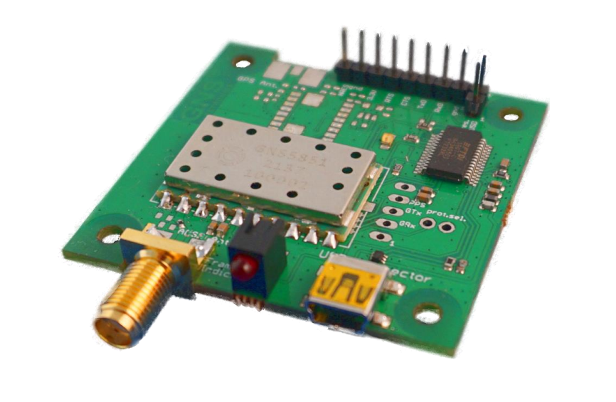
This Quick Guide is a short summary of the most important features of the GNS5851 StarterKit. This manual shows how to connect the GNS5851 StarterKit to a PC in order to verify GNS 5851 AIS Receiver module performance and test supported features.
For technical specification, please refer to the GNS5851_AIS_receiver_datasheet.
Connected to a PC, all AIS NMEA Data is routed to the Mini-USB port.
|
| Features |
|
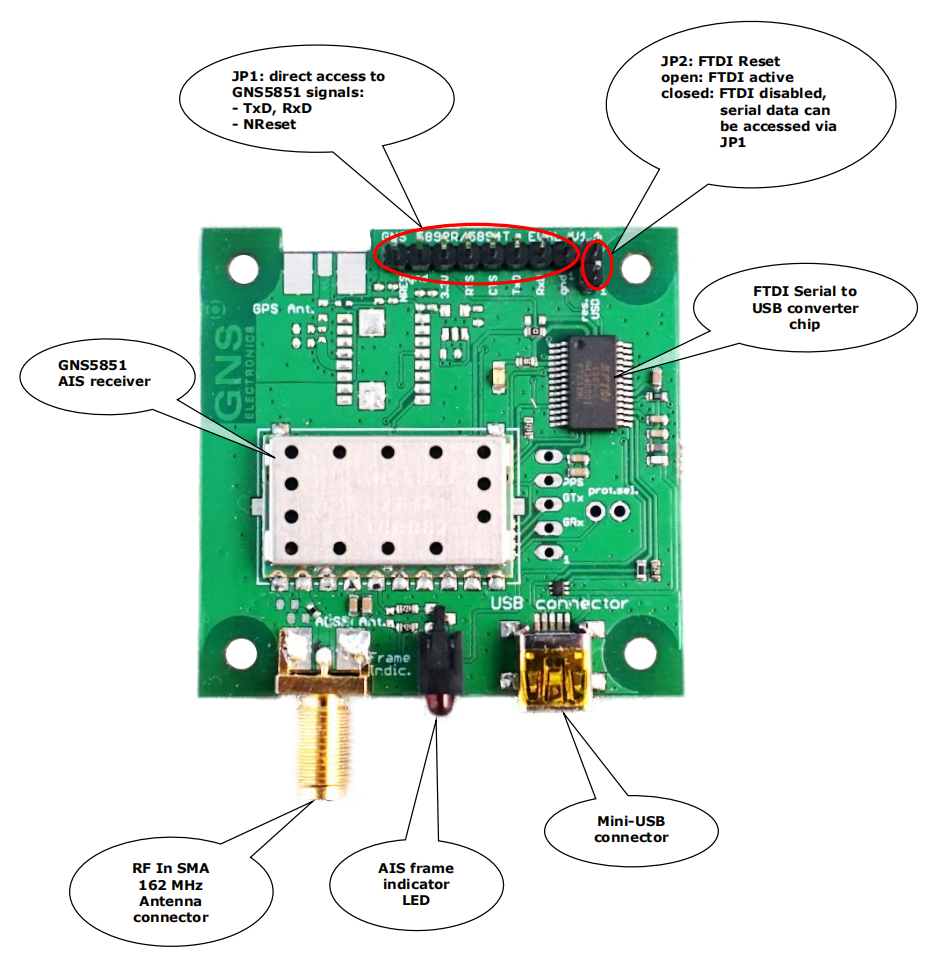
• Power supply via Mini-USB socket
• Access to all signals of the GNS 5851 via pin header contacts.
• PC data connection via the integrated USB to UART converter or direct access to the serial interface (3.3V) of the GNS 5851 for connection to other data processing devices.
• SMA antenna connector for 162MHz VHF RF In
• AIS “Frame Indicator” LED provides optical reception indication
|
| Description of the GNS5851 StarterKit |
|
The GNS 5851 StarterKit package includes the following items:
• GNS 5851 StarterKit PCB, fully populated and tested
• Aluminium housing (with PCB installed)
• AIS VHF antenna
• USB-Cable (USB-A to Mini-A)
Since the GNS 5851 module has the same pinout as the GNS 5892R and GNS 5894T modules, they share a single StarterKit PCB design. Depending on the production batch, your board might be marked as GNS 5851, GNS 5892R, GNS 5894T or a combination thereof. For the same reason, parts of the board may be unpopulated because they are only significant for other modules.
|
| USB Driver Installation |
|
The GNS 5851 Starter kit features an FTDI USB-to-UART bridge which may need a manually installed driver to properly work.
Windows 10
If Windows does not recognize the FTDI bridge automatically, the appropriate driver needs to be installed manually. Both the driver and the Installation Guide are available from FTDI through the following link under the section Virtual COM Port Drivers: https://ftdichip.com/drivers/vcp-drivers/
Linux
The FTDI Virtual Com Port (VCP) driver is built into the Linux kernel. VCP devices will appear as /dev/ttyUSBx
MacOS
While GNS-Electronics does not fully support macOS as a development platform, limited driver support is available from FTDI’s VCP-Driver web-page: https://ftdichip.com/drivers/vcp-drivers/
|
| |
|
JUMPER AND CONNECTOR DESCRIPTION
| CONNECTOR |
PIN |
SIGNAL |
DESCRIPTION |
| JP1 |
|
2: RxD (GNS5851 ser. input)
3: TxD (GNS5851 ser. output)
4: N.U. (marked CTS)
5: N.U. (marked RTS)
6: 3.3V
7: GND
8: /RESET GNS5851, active LOW |
Direct access to GNS5851 UART.
UART I/O Voltage is 3.3V. |
| JP2 |
|
1: GND
2: \RESET FTDI, active LOW |
Open: Operation via USB Port
Close: USB to serial converter is disabled, ser. Port (JP1) can be accessed. |
Description of AIS frame indicator
| AIS frame indicator |
Comment |
| flashing |
AIS frames are received and output via the serial interface. |
| Off |
No data is received |
|
| GNS5851 StarterKit Board Block Diagram |
|

Getting started
1. Connect the antenna to the GNS 5851 StarterKit
2. Connect the GNS 5851 StarterKit via USB to a Windows PC
3. After a few seconds the device is ready for use and is displayed in the device manager as "USB Serial Port" under the category "Ports”. Please refer to chapter 2 if the driver is not installed automatically.
|
| GNS5851 StarterKit Hardware |
|
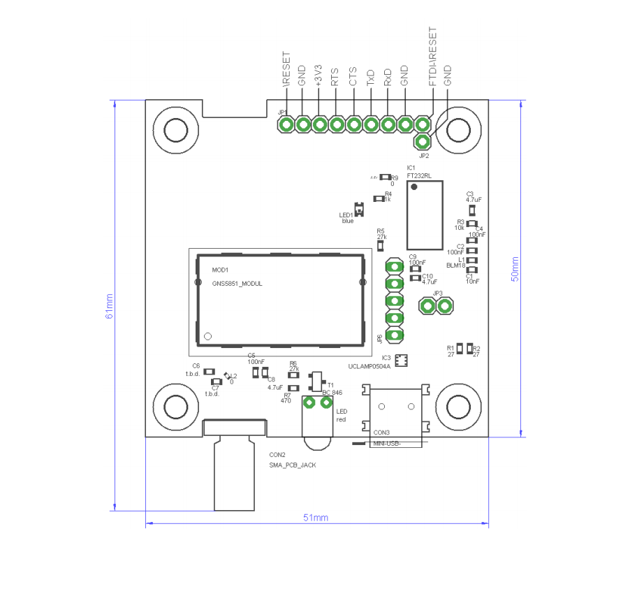
Assembly Drawing Top Side (with dimensions)
GNS 5851 StarterKit Schematic
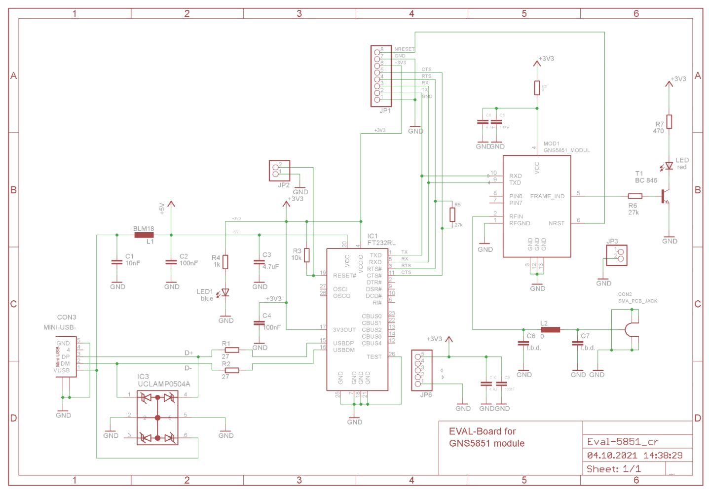
PCB Layout
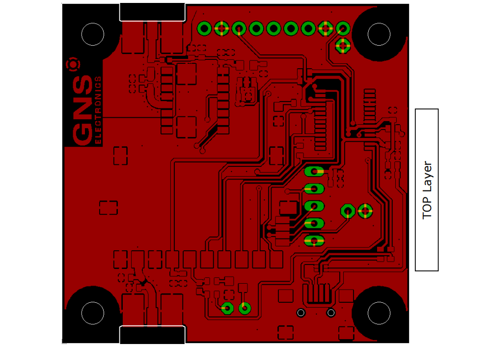 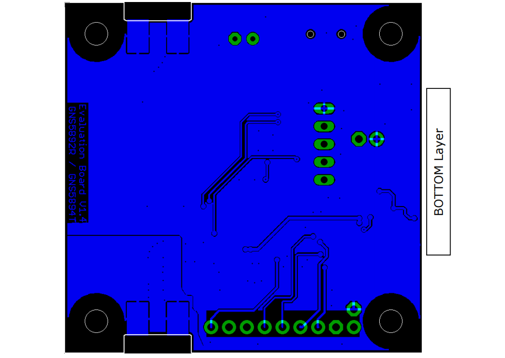
|
 GNS5851 StarterKit QuickGuide


