|
GNS5892R is a high performance receiver for ADS-B.
Due to high input sensitivity it can work directly with a passive antenna.
The improved RF architecture and outstanding decoder circuit together with the enhanced firmware provides maximum performance at minimum space and power requirements.
GNS5892R features a special ultra fast level adaption circuit that overcomes the so called "doughnut effect".
This input stage allows to receive very strong "near" and and very weak “far” signals at the same timewithout losses.
GNS5892R includes a complete ADS-B receiver. An appropriate power supply of 3.3V and a special antenna must be connected for operation.
- The signal picked from air is filtered and decoded without any host processing requirements.
- ADS-B –S data is provided at the serial UART port with a baudrate of 921kbaud. An appropriate host system with application must read and interprete the data and present them through the UI.
- No external clocks are required.
UART Interface details
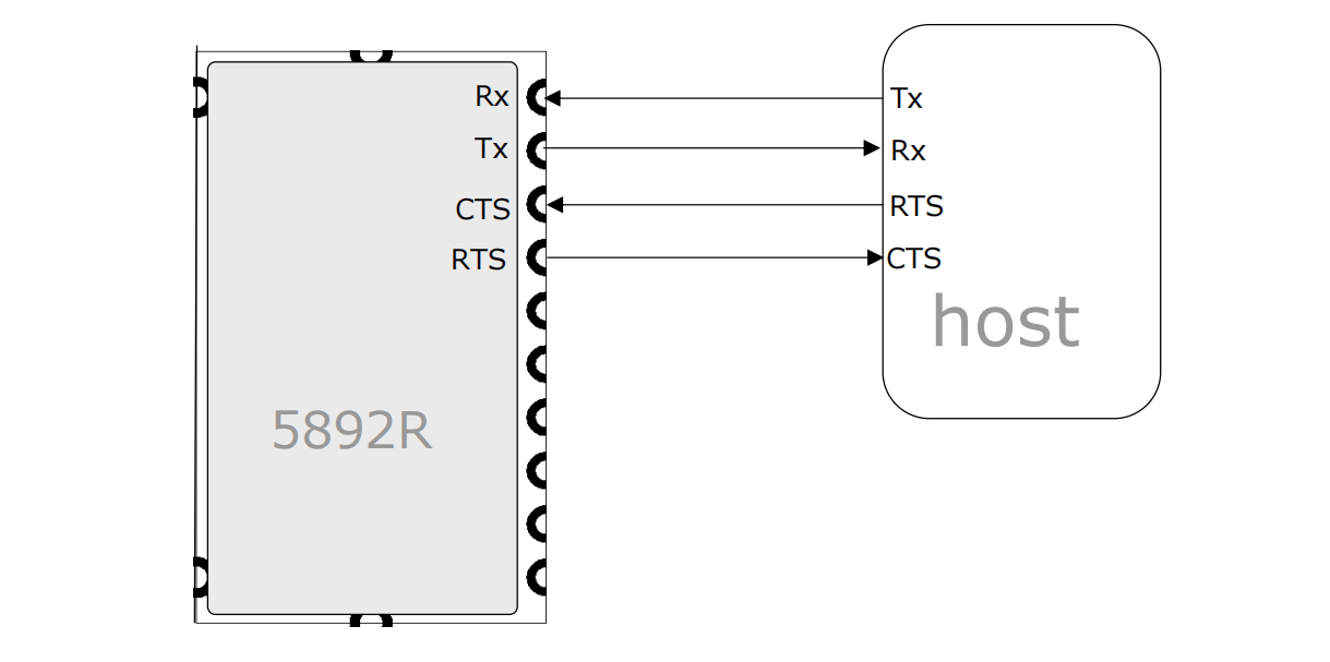
GNS5892R must be connected to the host system by a UART Interface.
• The UART interface is used to send ADS-B text messages and receive control messages.
• The default baud rate is 921600 baud, this baudrate is needed to transport the data without any data losses.
• For safe communication, implementing hardware handshake via RTS and CTS is recommended.
• I/O levels are 3.3V (see electrical data)
| GPS UART Default Settings |
| Parameter |
Value |
| Baud rate |
921,600 |
| Data length |
8 bits |
| Stop bit |
1 |
| Parity |
None |
| Handshake |
hardware |
The idle state of the UART lines is positive voltage. To interface a standard RS232 UART (e.g. a PC serial interface), please add an inverting level shifter. To interface processors that have a different interfacing voltage level, level shifters are required.

Power supply
GNS5892R needs a single power supply of 3.1..3.5V. The current consumption is ~40mA at full operation.
The power supply should be well filtered by placing a minim.10uF tantalum in parallel with a 100nF ceramic capacitor as near to the Vdd pin (4) as possible.
Reset input
The reset input is optional. Drawing this pin to low will reset the internal microprocessor. Reset can be left open for the most applications.
Frame available output
The frame available signal is used to indicate frames being successfully decoded.The pin will be set to high for 1ms whwnever a frame comes in. The signal can be used by a host processor or may drive a LED to provide a visual feedback of the incoming data frames.
RF input (RFin)
The RF input pin has a nominal impedance of 50 Ohms. Please keep tracks from module to antenna connector as short as possible. If more than a few millimetres track length is needed, the tracks must be impedance controlled (e.g. microstrip line). Please remember that the signal frequency is over 1 GHz.
For connecting the antenna, a SMA or MCX connector should be used.
On request, GNS can offer RF-support regarding PCB design.
ADS-B antenna
Depending on the application, a small rod antenna of just 20cm length can be used. This will provide arange of up to 200km around your location. However, using a high gain antenna will offer much more range and continous tracking. Both types of antenna a available from GNS.
For antenna installation, it’s important to know that ADS-B signals will spread linear only. Any obstacles like buildings, mountains or woods will mute or even totally block ADS-B-signals.
Antenna should be mounted to have an unobstructed "view" in all directions from a raised location.
ATTENTION: Risk of fire and injury ! For any raised mounted antenna constructions like roof antennas or aerial masts, it’s mandatory to follow the rules for lightning protection.
In case of doubt please consult a professional specialist |
|


